Config : Controller - Trajectory Planner
Overview
Trajectory Planner is a package that is used to drive the robot. It issues the linear and angular velocity commands that are needed to reach the goal. Trajectory Planner in itself does not map a path to the goal; it focuses on following the global path to the goal efficiently.
For a more relatable example, think about how GPS apps map out a path to a destination from a start location, It is up to the driver of the vehicle to follow the path while avoiding other cars, obstacles, speeding up, stopping at traffic lights, etc. Trajectory planner is meant to replicate the ‘driver’ and choose the best course of action to follow the path to the destination.
Working and Description
Think about how a driver of a vehicle makes simple decisions while following the route given by a GPS app. The driver may choose to accelerate the vehicle or slow it down or turn the steering left or right to add curvature to the vehicle’s path. It is reasonable to say that the driver is subconsciously thinking about each combination of the accelerator pedal and the steering wheel and choosing the best of these combinations. Which combination is the best depends on answering questions such as:
- Does this combination allow me to reach the goal quickly?
- Am I running into obstacles if choose this combination?
- Will I stay on the course described by the GPS?
He or she evaluates each combination and chooses the optimal one. This process repeats until the driver reaches the goal.
Trajectory Planner tries to replicate this approach. It takes a set of linear velocities and angular velocities. It then checks the validity of each combination of the two velocities and discards it if invalid. For example, a combination can be invalid if it causes the robot to hit an obstacle.
If the combination is not invalid, a ‘score’ is assigned to it on the basis of several parameters. The scoring process is analogous to the driver of the vehicle choosing the best course of action in the scenario given before. The scoring parameters include, but are not limited to:
- Proximity to obstacles
- Proximity to the goal
- Proximity to the global path
- Speed
Tweaking these scoring parameters effectively allows for better navigation and is critical to the Trajectory Planner algorithm.
Robot Parameter Description
We previously saw that tuning the trajectory planner’s scoring parameters is important for properly following a path and avoiding obstacles. Before going into the scoring parameters, it is important to let Trajectory Planner know about your robot. Just like the driver knows about his or her vehicle, its acceleration potential, turning radius, braking distance, etc, Trajectory planner also needs to know this information about the robot.
1. Robot Configuration Parameters
| Parameter | Units | Description |
|---|---|---|
| max_vel_x | S.I | Maximum possible Linear Velocity |
| min_vel_x | S.I | Minimum possible Linear Velocity |
| max_vel_theta | S.I | Maximum possible Angular Velocity |
| min_vel_theta | S.I | Minimum possible Angular Velocity |
| min_in_place_vel_theta | S.I | Minimum possible Angular Velocity when the robot is turning about its axis and not in linear motion. |
| acc_lim_x | S.I | Maximum possible Linear Acceleration |
| acc_lim_y | S.I | Maximum possible Linear Acceleration along y axis (consider positive x-axis to be forward for the robot. Usually this value is set to 0). |
| acc_lim_theta | S.I | Maximum possible Angular Acceleration |
2. Goal Tolerance Parameters
| Parameter | Units | Description |
|---|---|---|
| xy_goal_tolerance | S.I | Maximum allowable deviation in robot position from the goal position. |
| yaw_goal_tolerance | S.I | The goal also specifies the direction in which the robot faces at goal-position. This parameter specifies the maximum allowable angular deviation in the robot orientation from the goal orientation. |
3. Differential-Drive Robot Configuration
| Parameter | Values | Description |
|---|---|---|
| holonomic_robot | true/false | If robot uses differential drive or cannot move along y-axis, set this to false. If robot can also move in y-direction without turning (eg mecanum wheels), set this to true. |
4. Forward Simulation Parameters
These parameters affect how linear velocity and angular velocity pairs, also called (v, w) pairs, are created or declared invalid.
| Parameter | Units | Description |
|---|---|---|
| sim_time | seconds | A small simulation is run with the (v, w) pair. If the robot collides with an obstacle for the given v and w, the pair is declared invalid. sim_time controls how long this simulation runs for. |
| vx_samples | Number | Number of samples to take for linear velocity |
| vtheta_samples | Number | Number of samples to take for angular velocity |
| sim_granularity | Number | Granularity defines the step size between points on a trajectory. Each point is checked for collision, so lower granularity means testing more points and using more computation resources. |
| angular_sim_granularity | Number | Granularity for angles. Used for orientation instead of position. |
| heading_lookahead | Number | Lookahead for the sim |
5. Robot Footprint
| Parameter | Values | Description |
|---|---|---|
| type | “circular”, “polygon” | Type of robot. |
| radius | (Numeric) eg. 0.2 | Radius for circular robot |
| vertices | (List) eg. [[-0.205, -0.155], [-0.205, 0.155], [0.077, 0.155], [0.077, -0.155]] | List of vertices for the robot polygon. |
| padding | (String) eg “0.01 | Padding for the robot. Think of this as extra distance from the robot for safety reasons. |
6. Cost Footprints
| Parameter | Values | Description |
|---|---|---|
| pdist_scale | (Numeric) eg 1.8 | Increasing this value makes the algorithm prefer paths that are closer to the global path |
| gdist_scale | (Numeric) eg. 1.0 | Increasing this value makes the algorithm prefer paths that are closer to the goal. |
| occdist_scale | (Numeric) eg. 0.4 | Increasing this value makes the algorithm prefer paths that are farther from obstacles. Try increasing if the robot is straying too close to obstacles. |
Files to alter for Tuning
The following files need to be altered and saved for custom parameters to take effect.
1. turtle_mowito
| Trajectory Planner | mowito_ws/src/turtle_mowito/mowito_turtlebot/config/controller_config/trajectory_planner_ros.yaml |
| Local Costmap | mowito_ws/src/turtle_mowito/mowito_turtlebot/config/costmap_config/local_costmap_params.yaml |
| Global Costmap | mowito_ws/src/turtle_mowito/mowito_turtlebot/config/costmap_config/global_costmap_params.yaml |
2. rosbot
| Trajectory Planner | mowito_ws/src/gazebo_sim/src/rosbot_description/config/controller/trajectory_planner_ros.yaml |
| Local Costmap | mowito_ws/src/costmap2d/config/local_costmap_params.yaml |
| Global Costmap | mowito_ws/src/costmap2d/config/global_costmap_params.yaml |
Common Problems and Tuning
This section describes certain common problems and describes in more detail how changing parameters will affect the robot behaviour.
Tip
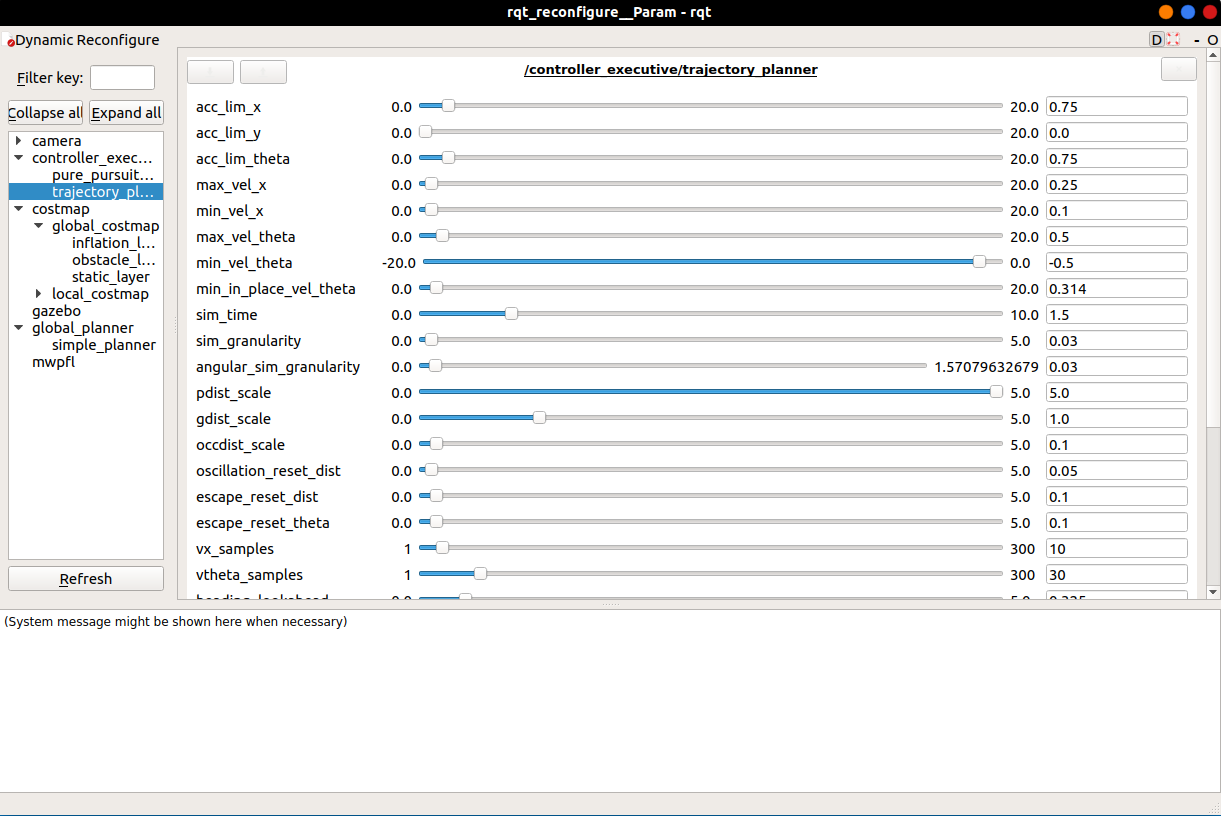
Traditionally, one may edit and save the parameter files and relaunch the navigation to see their affect. It is highly recommended to use rqt_reconfigure, a ros utility that allows changing parameters during execution. Thus, there is no need to relaunch the navigation node(s). To use rqt_reconfigure, open a separate terminal (source the ros) and run
rosrun rqt_reconfigure rqt_reconfigure
A window like this would appear
Usage
- Make sure all parameters have the correct values.
- Change the values using either the sliders or the boxes next to the sliders
- After tuning, make sure to save your new parameters by changing them in the files listed above so that they are loaded each time the navigation is launched.
- It is recommended to make a backup of the original parameter files.
A. Local path is curving a lot and causes the robot to be slow and move in a sine wave-like path.
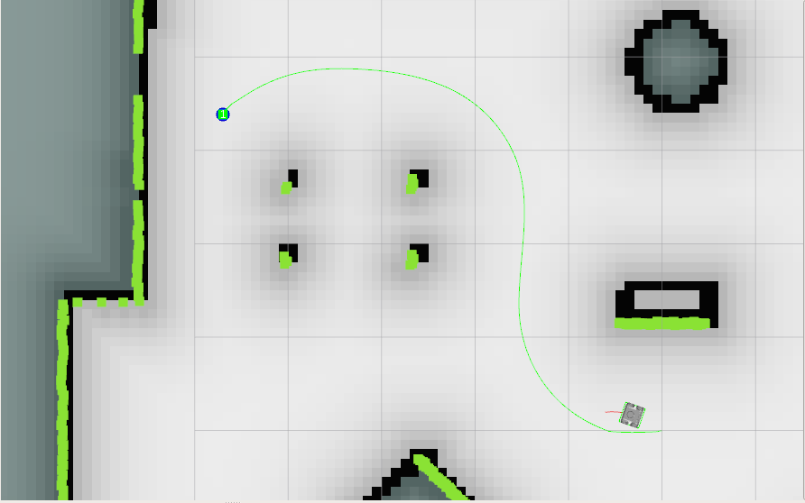
This happens because of the path cost solution (pdist_bias, gdist_bias and occdist_bias params) Increasing the pdist bias will cause the robot to move closer to the global path, thereby reducing the ‘sinusoidal’ behaviour of the robot.
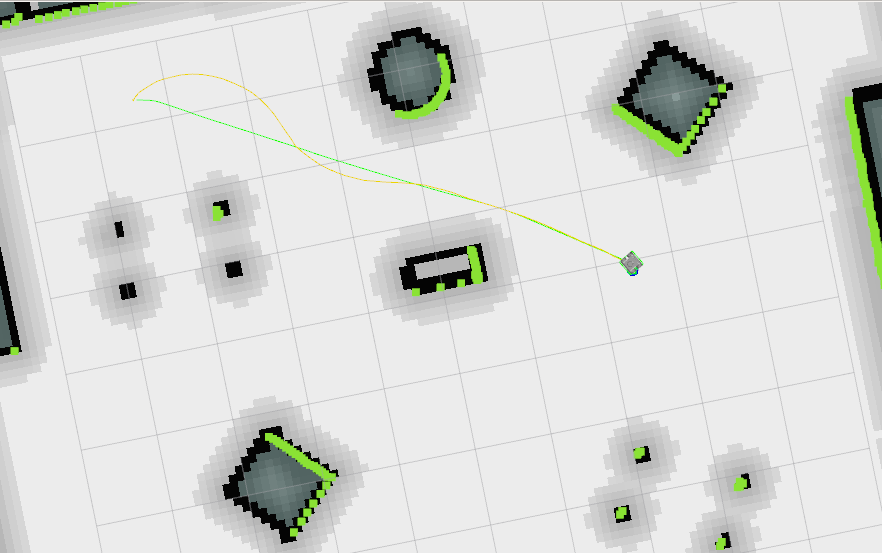
pdist_bias is set to 1.5
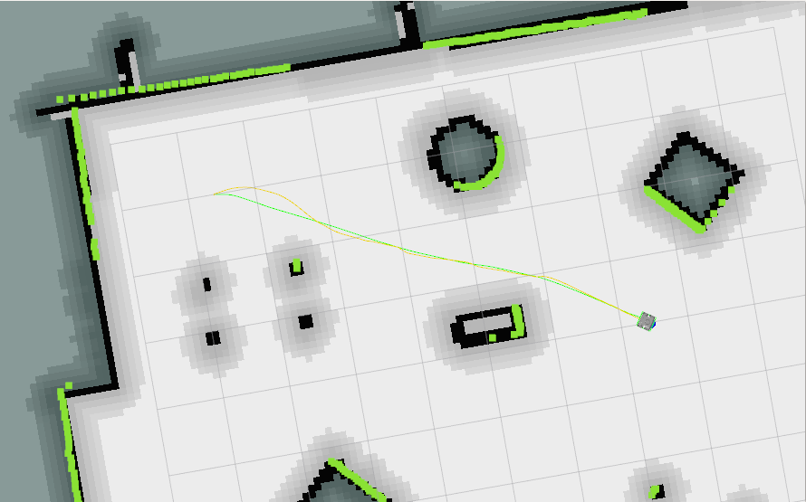
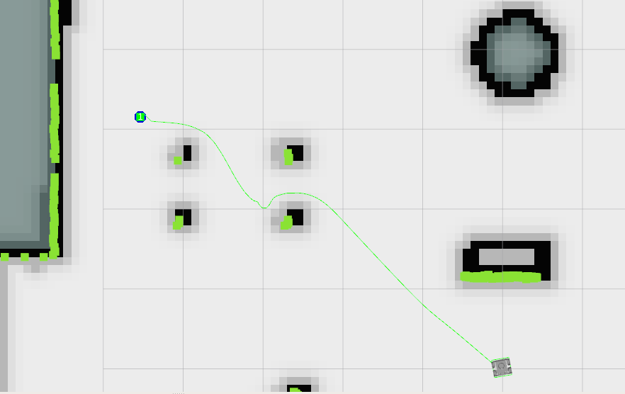
pdist_bias is set to 4.0
B. The robot is not following the global path that goes between obstacles when the opening is small or the robot comes close to the obstacle and gets stuck.
The robot comes close to obstacles because either the global path or the local path is not far enough from obstacles. It is suggested to tweak the inflation_radius and cost_scaling_factors to avoid this.
Obstacles exert a ‘cost’ on the map. For this purpose, the map is divided into a grid-based on a resolution. Think of this as pixels on a screen. A higher resolution means more points on the map. For each point, the cost is calculated. Thus, a higher resolution would require more computation power. Keep in mind that the resolution should be lower than that of the laser scanner hardware mounted on the robot.
The collection of all these points with their costs is called a ‘costmap’. The cost of each pixel is used to determine how close the robot is to the object relative to how close it should be. This is not an actual estimate, only a numerical one that scales inversely with distance to the object and gives the robot a sense for how close it is to an obstacle. For example, the points close the obstacle will have a cost value close to 255, and cost would decrease the farther away we go from the obstacle. The rate of decrease and the limit of the obstacle’s influence can be changed by tweaking the inflation_radius and cost_scaling_factor.
Inflation radius Inflation radius sets the absolute limit till which an object exerts influence or cost. Starting from the inflation radius and beyond, the costmap will have 0 cost due to the obstacle.
Cost Scaling Factor This factor defines how steeply or gradually the cost will decrease as we move farther away from the obstacle. It is inversely proportional to the cost of a cell. So a higher value means the costs decrease quickly as we move farther from an obstacle. A lower value would lead to a more gentle slope.
It is recommended to set inflation_radius and cost_scaling_factor such that slopes are gentler and move a decent distance away from the obstacle. This allows the global path planner and trajectory planner to find the ‘midway’ path between obstacles and not stray too close to one obstacle. In the examples below, a higher cost is indicated by darker shade for the ‘pixel’ or grid-cell.
inflation_radius: 0.2, cost_scaling_factor: 3.0
inflation_radius: 1.5, cost_scaling_factor: 3.0
Notice how in the first case, the global path goes close to the obstacles, while in the second case, a path that is roughly equidistant from all obstacles is chosen.
inflation_radius: 1.5, cost_scaling_factor: 15.0
Notice how in this case, the scaling factor is high and the costmap around obstacles is steep. This means the cost reaches zero quickly and the global path changes. While this may look similar to the first case, notice that in the first case the costmap slope is gradual but the inflation radius is short and the costmap around an obstacle terminates quickly because of the short radius. In this case, the radius is more than enough but the costmap is steep and reaches zero cost.
Ths same parameters are also tweaked for the local costmap used by the trajectory planner (Yes, the costmap used by the global planner is global costmap, while that used by trajectory planner is local costmap).
For instance, take global costmap parameters as:
- inflation_radius: 0.2
- cost_scaling_factor: 3.0
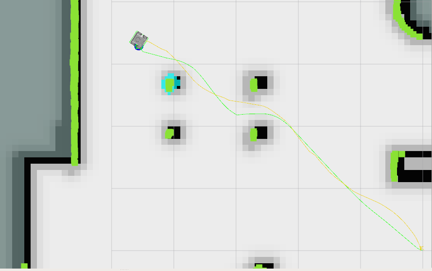
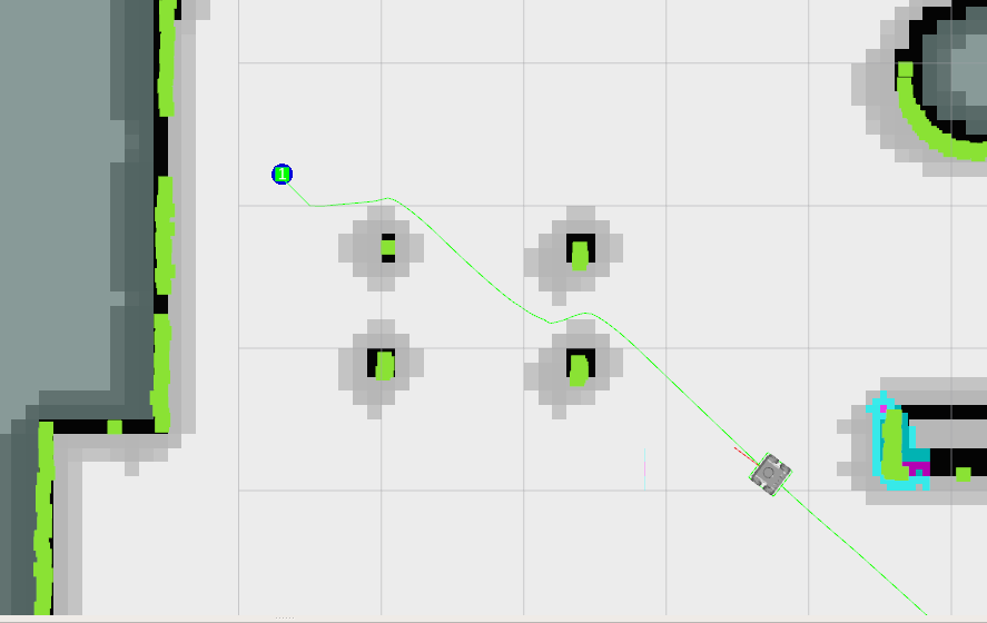
Local Costmap cost_scaling_factor: 3.0, inflation_radius: 0.1
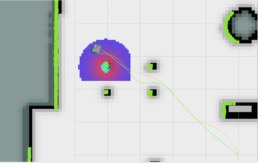
Local Costmap cost_scaling_factor: 3.0, inflation_radius: 0.8
Notice how the robot is considering a larger area and that the path it took is relatively farther from obstacles than it is in the first case. The change can be increased by tuning the cost_scaling_factor and inflation_radius. If the inflation radius is too large, the robot may try to avoid narrow pathways.
C. The calculation needs too much time to stay at moving frequency
The number of times this warning occurs can be reduced by tweaking parameters to use less computational resources. Try reducing local costmap width and height. This is an effective method to reduce computation time.
Other methods to reduce computation time:
- Increase sim_granularity
- Reduce vx_samples and/or vtheta_samples
- Reduce sim_time
D. The robot is able to reach the first goal but fails for subsequent ones.
The cause is unknown. Reducing heading_lookahead for trajectory planner may fix the issue. Try the value 0.325